The blurring line between oscilloscopes and On-Die instrumentation
"At 28 Gbits/sec everything matters," says Dave Dunham, Director of signal integrity at Molex. Even above 5 Gbits/sec, interconnects are no longer transparent. The beautiful, clean, pristine signals from the pads of the die get distorted, attenuated and turned to mush by IC packages, circuit board traces, connectors and cables.
Limitations from the fundamental physics of interconnect losses can’t be eliminated. The only practical way around this limitation in the interconnects is to implement significant signal processing on-die at the transmitter in the form of FFE (feed forward equalisation) and on-die at the receiver in the form of CTLE (continuous time linear equalisation) and DFE (decision feedback equalisation).
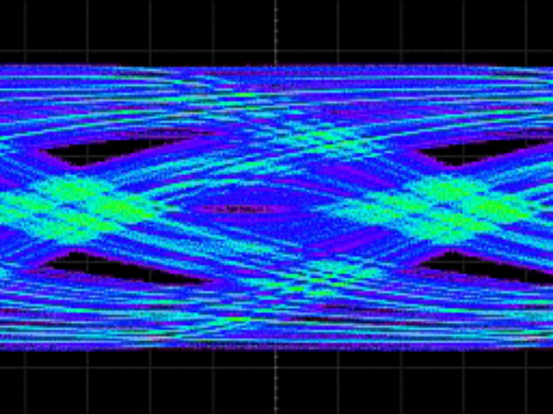
Interconnects can distort a signal so much that at the receiver’s pads, an eye diagram can be completely closed. On-die signal processing can open the eye. Figure 1 shows an example of the measured real time signal and resulting eye as measured at the pads of the receiver package, before the on-die equalisation has a chance to clean it up.

Figure 1. A eye diagram at the pads of a receiver package before any equalisation shows how interconnects can distort the signal and close the eye.
Upon looking at the measured real-time signals, you can’t determine if on-die equalisation circuitry can clean the eye, recover the embedded clock and interpret the signal at an acceptable bit error ratio. Both the test and measurement industry and the semiconductor transceiver providers have responded to this challenge with innovative solutions, borrowing a little from each other.
As a result, oscilloscopes from the top test and measurement instrument providers—Agilent Technologies, Rhode Schwartz, Tektronix, and Teledyne LeCroy—have implemented the same equalisation techniques and CDR (clock data recovery) algorithms as found in typical receivers, to emulate what the receiver might see.
"The actual signal on the pads of the receiver chip can be so distorted above 5 Gbits/sec that we have to clean it up before we can even say if it is good or bad," said Alan Blankman, product manager for serial data analyser products at Teledyne LeCroy. "We’re careful to use the same algorithms in processing the signals measured by the scope as used in the receiver circuitry itself. This gives the engineer a realistic view of what the receiver would actually see."
An on-die CTLE filter is defined by a few simple pole-zero parameters. These can be selected based on the actual values used by the receiver, or optimised with software resident in the scope to maximise the eye opening. Figure 2 shows an example of the impact from the CTLE filter in the scope on the measured eye before and after the filter is applied.

Figure 2. Measured eye at the input to the CTLE filter implemented in the scope and the resulting eye.
After the CDR algorithm, the same DFE filter on-die is implemented in the scope to replicated the final eye opening that would appear at the receiver. This filter will take a fraction of a few previous bits and add them to a later bit. The fraction of each prior bit is the "tap coefficient." The coefficient values used in the scope can be selected as the same ones used on-die, or optimised based on the maximum eye opening. Figure 3 shows an example of the impact on the measured eye after the CDR and DFE filter are applied in the scope.

Figure 3. Final signal emulated by the scope based on the CTLE, CDR and DFE features that would be implemented on-die at the RX.
next; scope functions on-the-die
Another approach taken by some semiconductor providers is to add oscilloscope functions on-die. The two leading FPGA vendors, Xilinx and Altera, have implemented "embedded instruments" on their latest 28 Gbit/sec designs.
In the Xilinx ChipScope Pro family of IP tools, internal circuitry samples the on-die signals at various locations and performs analysis to evaluate signal quality, margin and bit error ratios. The Eye Scan tool allows the export of the sampled eye after the DFE filter to show the eye the receiver actually sees. Figure 4 illustrates where this is implemented in the receiver.

Figure 4. Implementation of the Xilinx Eye Scan, part of the ChipScope Pro IP suite available on all receiver channels in the latest Virtex 7 FPGA designs.
"The Eye Scan results provide important information for validating the design of each channel across voltage, temperature and process," Luis Bielich, applications engineer with Xilinx comments. "Along with the ability to validate the design of a channel, Eye Scan also provides a very high level of debug information not previously available in FPGA families."
Altera’s version of on-die instrumentation is the EYEQ IP core. The signal is sampled internally after the equaliser and the clock data recovery circuitry. A sampler is used to select 32 horizon and 64 vertical measurements to recreate the eye as it would appear into the deserialiser. Figure 5 shows how EYEQ is implemented.


Figure 5. Block diagram of the Altera EYEQ IP block implemented at the RX (top) and the resulting eye showing the time and voltage sampling positions (bottom).
"This architecture provides non-destructive measurement capability to simultaneously measure both bit errors and eye samples," Lux Joshi, product manager for Stratix V FPGAs at Altera notes. "In addition to collecting samples at various sampling times and voltage levels, a hardened serial bit checker allows reconstruction of eye measurements as well as BER contours using either random data or repeating data patterns. This information provides key insights into link margin in system."
When interconnects distort signals so much that they become totally unrecognisable and unusable, new approaches have to be implemented to measure signal integrity. New features are making oscilloscopes look more like the silicon they are testing and the silicon now looks more like the instruments that test them.
About the author
Eric Bogatin is a signal-integrity evangelist at Teledyne LeCroy. He holds an SB degree in physics from MIT and a PhD in physics from the University of Arizona in Tucson. He has been active in the signal-integrity industry for more than 30 years, writing articles and books and teaching classes. eric@bethesignal.com.
 If you enjoyed this article, you will like the following ones: don't miss them by subscribing to :