Improving reliability and lowering audible noise on LED drivers
LEDs are up to 30% more efficient, but with this, dimming becomes more challenging. The main point is the shift in the light spectrum, which occurs when the LED forward current changes. So simply reducing the current reduces the brightness but brings an unwanted shift of the colour temperature. Funnily enough, the change of the luminous colour of a normal light bulb to reddish when it is dimmed appears to be desired and enjoyable.
For LED-lighting, this effect is not wanted and the colour temperature should be maintained. Therefore, the dimming is implemented via PWM dimming where the nominal current is applied to the LED but it is switched on and off very fast.
Doing this, the RMS and average current become lower and so does the brightness. At the same time the colour temperature stays the same as the LED is always driven with its nominal current. The PWM dimming frequency should be above 100 Hz to avoid visual flickering and is ideally in the range of 100-300 Hz to minimise the switching losses.
In the following paragraphs we will see why it can be a good idea to use ceramic capacitors instead of electrolytic capacitors. We will also discuss the influence on output voltage ripple and how problems with audible noise due to PWM dimming are resolved.
Reliability
LED drivers are mostly mounted in constricted spaces where it can become hot and they are not easily accessible. Therefore, it is very important that LED drivers work reliably over a long period of time. The main reason for failing electronics, especially switch mode power supplies, are broken electrolytic capacitors.
On a boost converter, high current ripple is seen at the output, which stresses the capacitors. So an electrolytic output capacitor on a boost LED driver not only has to handle the current ripple but also withstand high temperature for several years. To avoid this problem, X7R ceramic capacitors should be used. They can handle high current ripple without any problems and work reliably even under higher temperatures – unfortunately, this causes new problems.
Problem number one is the comparatively low capacitance of ceramic capacitors. For a boost LED driver reference design with 24V input and 40V output voltage, ceramic capacitors with 2.2uF (100V, X7R, 1210) are selected for the output. Where typically 100uF or more for an electrolytic capacitor is used in this kind of application to achieve a low voltage ripple on the output, it’s simply impossible to do this with ceramics due to cost reasons. Though one or two of the named ceramic capacitors are not enough for attenuating the voltage ripple. The solution is adding a post-filter as shown in figure 1.

Fig. 1: Boost power stage with post filter
The two capacitors directly connected to the diode catch the pulsed current of the boost power stage and average it to a DC voltage still with a significant ripple. Adding an L-C post filter with a corner frequency of about 1/10 of the switching frequency decouples the output voltage from the ripple which is seen at C2 and C3.

Fig. 2: Voltage ripple before post filter
The measurement shows attenuation by a factor of about 77 (385mV vs. 5mV / 38 dB) which results in a smooth and clean output voltage for driving the LEDs. The damping of 38 dB (which is close to the theoretical 40 dB of an L-C filter) only applies to the ripple caused by the pulsed current of the converter’s switching frequency. The damping of high frequency spike – see figure 3 – is only around 7 (385mV vs. 58mV / 16 dB).

Fig. 3: Voltage ripple after post filter
This is due to the interwinding capacitance of the inductor, which lowers the attenuation for high frequencies. To get rid of these spikes, ferrite beads for high frequencies must be added.
The before mentioned post filter can also be used if large bulk electrolytic capacitors on the input or output of a switch mode power supply are needed, but the designer has to have a low cost solution. By simply decoupling the capacitors from the AC currents with a tiny inductor, the system becomes much more reliable without overstressing the electrolytic capacitors.
Audible noise
Ceramic capacitors allow engineers to design LED drivers for a wide operating temperature range and long lifetime. But there is a big challenge when PWM dimming has to be implemented. The PWM signal with a frequency of several hundreds of Hertz switches the LED current on and off with the same frequency. This pulsed current is seen by the ceramic capacitors at the output of a boost LED driver causing them to resonate mechanically due to the piezoelectric effect.
The capacitors start to move up and down with the frequency of the PWM and stimulate the PCB, which acts as a loudspeaker. Dependent on the current and mechanical setup this noise can be very loud and annoying. There are special ceramic capacitors available with a smaller distinctive effect, but only a very good layout and mechanical setup can solve this problem effectively.
It reduces the noise to an acceptable volume. If this is done, standard ceramic capacitor can be used. First of all, place two identical capacitors directly opposite each other on the top and bottom side of the PCB. If there is only a single capacitor, it bends its middle towards the PCB and back. In doing this, the PCB is stimulated like the membrane of a loud speaker and emits acoustic waves. If two capacitors are placed opposite one another, both bend towards and away from the PCB at the same time. Thus, the PCB cannot resonate anymore.
The second action to reduce the residual noise further is to minimise the mechanical coupling of the ceramic capacitors and the PCB. By milling holes into the PCB besides the solder points, the stimulated PCB area is reduced significantly. Figure 4 shows the read marked holes in the PCB around the ceramic capacitors.

Fig. 4: PCB cutouts around the ceramic capacitors
By implementing the two methods mentioned above, the audible noise is heavily reduced. Without these arrangements, the noise caused by the PWM dimming and the ceramic capacitors on the output of a boost LED driver is clearly heard up to a few meters away. By limiting the movement of the capacitors and minimising the resonating area of the PCB, the noise is reduced to such a low level that you need to put your ear as close as possible to the PCB to hear a residual very low buzzing.
Conclusion
Using ceramic capacitors instead of electrolytic capacitors for LED drivers reduces the form factor of the system and increases the reliability. An additional post filter consisting of a tiny inductor and ceramic capacitors reduce the output voltage ripple to a very low level.
The piezo ceramic effect seen with ceramic capacitors causes audible noise when PWM dimming is implemented. This noise is attenuated effectively by proper placement of the capacitors and small cut-outs on the PCB.
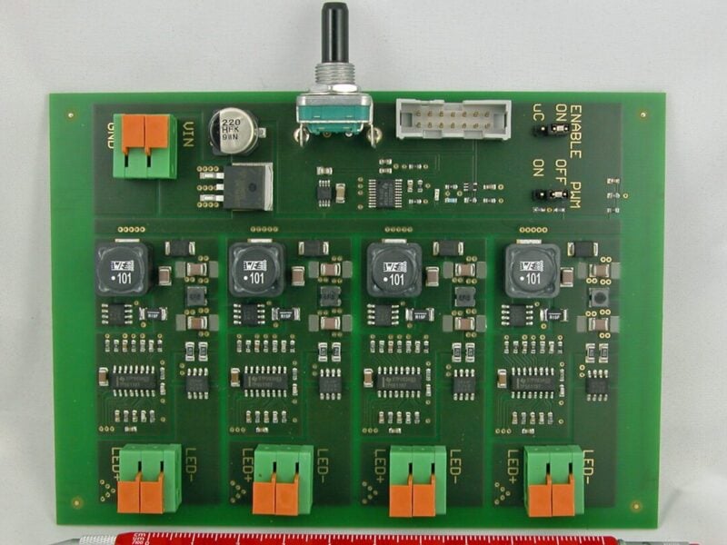
TI Design PMP10171 is a four channel boost LED driver with an input voltage range of 10-30V and 500mA at 40V output per channel. It incorporates the techniques described in this article and all the information (schematic, bill of material, test report, layout and firmware) is available on TI.com with PMP10171 as reference.

Fig. 5: Photo of PMP10171
About the author
Matthias Ulmann works in the EMEA Design Services Group of Texas Instrument – www.ti.com – as a Reference Design Engineer in Freising, Germany.
 If you enjoyed this article, you will like the following ones: don't miss them by subscribing to :