
How to make LED bulbs dimmable
For several years manufacturers have been introducing LED bulbs onto the market with the eventual goal of replacing incandescent and CFL lamps. The design of these lamps has evolved from very simple non-dimmable solutions, to sophisticated but expensive dimmable solutions, then finally to more cost effective dimmable solutions.
Many LED lamps are advertised as dimmable, however in reality the performance of many of them is unimpressive with varying results depending on the dimmer used and loading of the circuit. In some cases the LED lamp has been taken out of its box and installed in a room with a dimmer switch only to discover flickering and uneven adjustment of the light level.
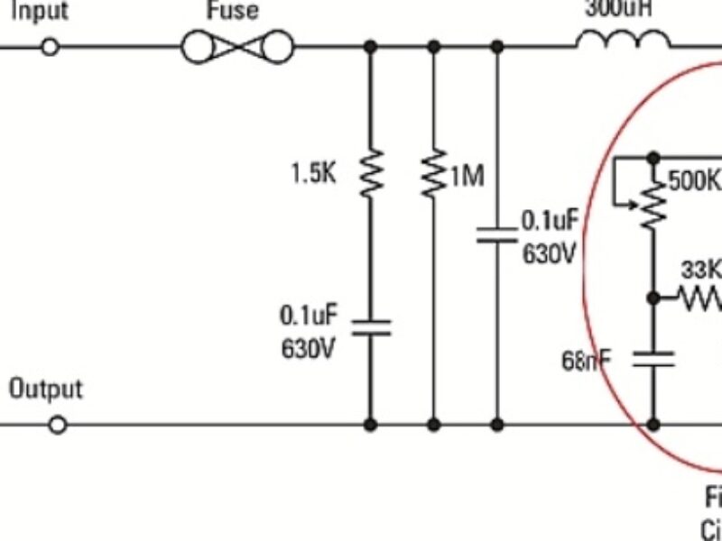
These deficiencies result from the fact that the vast majority of dimmers installed in the US are based on the triac-based two-wire leading edge phase cut circuit developed in the 1960s intended for use with resistive incandescent lamps. The triac, a bi-directional semiconductor power switch, is triggered by a pulse generated by a variable timing circuit and maintains conduction while its conducted current remains above a certain level termed as the holding current. There are many varieties of the dimmer circuit using devices with different characteristics combined with variations in the control circuitry and filtering components.

Figure 1 – A typical dimmer schematic
The LED lamp’s driver electronics converts AC input power to low voltage DC power and maintains a regulated current to drive the high-brightness LED load for constant light output. A basic LED driver circuit cannot be dimmed from a triac-based dimmer without some additional components being added to enable stable dimmer operation and then to adjust the output current based on the dimmer phase angle.
Since dimmers vary considerably it is inevitable that the performance of connected LED dimming circuits also varies. The issue becomes more confusing as there are currently no clearly defined standards for classifying performance of LED bulbs with dimmers. At most some bulb manufacturers provide lists of dimmers that they claim to be compatible with their product.
The National Electrical Manufacturers Association (NEMA) supported by the US Department of Energy (DoE) is now developing dimming standards for LED lights driven from phase cut dimmers, which will cover test procedures and metrics for determining whether acceptable performance has been met. Hopefully this much needed initiative will eventually remove products from the shelves that claim to be dimmable when performance is far below expectations of end users accustomed to smooth and stable incandescent dimming.
Driver electronics within most LED bulbs incorporate Buck, Buck-Boost or Flyback converters. In each case the basic circuit can be modified to make it dimmable with acceptable performance met without adding greatly to the component cost and complexity. The goal here is to provide dimmable drivers with good performance able to meet the aggressive cost constraints imposed by the consumer lighting market.
The problem of compatibility lies in how the triac dimmer circuit interacts with the input circuitry of the LED driver.

Figure 2 – Basic LED driver circuit blocks
The single stage LED driver example circuit above replaces the resistive load representing an incandescent lamp shown in Figure 1. Although this circuit mimics a resistive load due to its high power factor during steady state operation, the front end includes capacitors necessary for EMI filtering. The LED bulb also consumes less than 25% of the power of an equivalent incandescent. The result is that the dimmer sees a mainly capacitive load during the portion of the AC line half cycle before the triac fires.
The bi-directional firing circuit shown in Figure 1 requires a resistive path to neutral to operate as it was designed to. If instead the load is capacitive, this circuit cannot function correctly which will result in erratic firing from one cycle to the next that shows up as a flickering light output. The presence of EMI filters in the dimmer and the LED driver also creates ringing oscillations caused by the high dv/dt at triac switch on.
These oscillations, if large enough, can cause the current to fall below the holding current making the triac switch off instead of remaining in conduction until the next line zero crossing. This is often made worse by the firing circuit re-triggering the triac so that it switches on and off several times during a single line half cycle. Apart from stressing the components and quite possibly damaging the dimmer or LED driver this creates severe flickering and unpleasant audible noise.
Assuming that replacing the dimmer with one designed to operate with LED lamps is not the desired solution, the LED driver can be modified to eliminate the problem described above so that it may be used with a standard dimmer.

Figure 3 – Dimmable LED driver schematic
The above example circuit is a single stage LED Flyback converter; the same techniques can also be applied to a Buck-Boost or to an adapted Buck converter. Firstly it is necessary when designing the input filter to keep the input capacitance to a minimum, which also helps to attain the best possible power factor.
The next step is to introduce the active damper and passive bleeder circuits. The damper circuit limits the inrush current when the triac fires greatly reducing ringing so that the triac remains on. After a short delay the damper resistor gets bypassed by a small MOSFET to prevent power loss during the remaining conduction period. To reduce cost to a bare minimum for low power drivers the bypass MOSFET and its associated drive circuitry can be omitted, however this creates some heat dissipation in the resistor and associated efficiency loss.
The passive bleeder circuit can be used to replace active bleeders used in some dimming solutions. This series RC network conducts current from the firing point long enough for the switching converter to start drawing current. This helps to ensure that the current does not drop below the holding current during that period. The Flyback or Buck-Boost converter operating with constant on time appears as a predominantly resistive load to the DC bus allowing conduction to occur through the dimmer’s triac until the next line zero crossing. It is essential that the converter draws sufficient current to remain above the triac holding current. A single stage PFC Flyback or Buck-Boost converter is normally able to do this.
The circuit implementation here uses the IRS2983 controller IC, which operates in voltage mode. The DC voltage level present at the COMP input determines the on time of the switching cycle. Since the controller IC is typically used with primary side regulation to maintain a constant output power, it is necessary to clamp the COMP voltage by adding a zener diode to this input. This sets a limit for the maximum on time so that during dimming when the DC bus voltage drops the on time cannot increase to compensate.
The result is that as the dimmer setting is reduced and the DC bus voltage drops the output current also reduces. This allows the light level to be dimmed to less than 20% by adjusting the dimmer control without the need for more complex circuitry to detect the dimmer phase angle and regulate the output. It is also necessary to discharge the controller VCC supply during the dimming off period to ensure the IC operates only during the required period. A high voltage diode is connected from VCC to the DC bus to accomplish this.
The active damper and passive bleeder circuits may also be used with a Buck converter, however results depend on the LED voltage. Since the converter cannot draw current while the line voltage is lower than the output voltage the phase dimming operating range is limited. For this reason lower LED voltage is desirable, however this cannot be too low or the circuit becomes inefficient requiring an impractically large inductor. For a 120VAC system to retain a reasonable range of adjustment a good tradeoff for the LED voltage would be in the 20 to 40V range. A CCM Buck LED controller IC such as the IRS2980 maintains average current regulation to the LEDs while the unsmoothed bus voltage remains above the total LED output voltage.
The simple techniques explained here, when utilized with the type of LED converters described, can provide smooth and flicker free dimming with most triac based dimmers.
 If you enjoyed this article, you will like the following ones: don't miss them by subscribing to :


